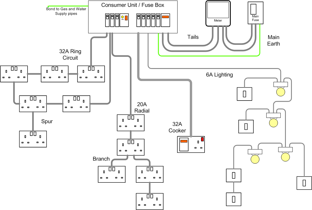
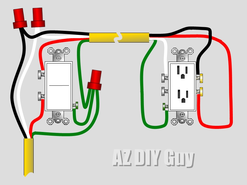
Basic Electrical Outlet Wiring Diagrams are crucial tools for understanding how electrical outlets are wired in a building. By having a clear picture of the wiring layout, electricians and DIY enthusiasts can ensure that outlets are installed correctly and safely.
Importance of Basic Electrical Outlet Wiring Diagrams
1. Ensure safety: Wiring diagrams help prevent electrical hazards by showing the correct way to connect wires and components.
2. Troubleshooting: Diagrams provide a roadmap for identifying and fixing electrical problems that may arise.
3. Compliance: Following wiring diagrams ensures that electrical work meets building codes and regulations.
Reading and Interpreting Basic Electrical Outlet Wiring Diagrams
1. Identify components: Understand what each symbol represents, such as outlets, switches, and wires.
2. Follow the flow: Trace the path of the wires to see how electricity is distributed throughout the circuit.
3. Note connections: Pay attention to how wires are connected and where they lead to ensure proper installation.
Using Wiring Diagrams for Troubleshooting
1. Locate the problem: Use the diagram to pinpoint where the issue might be occurring in the electrical system.
2. Check connections: Verify that wires are properly connected according to the diagram to rule out wiring errors.
3. Test components: Use the diagram to test outlets, switches, and other components to identify faulty parts.
Safety Tips for Working with Electrical Systems
- Always turn off the power before working on electrical systems to prevent shocks or injuries.
- Use insulated tools and equipment to avoid electrical contact.
- Double-check wiring diagrams to ensure correct connections are made.
- Seek professional help if unsure about any electrical work to avoid accidents.
Basic Electrical Outlet Wiring Diagram
Basic Electrical Outlet Wiring Diagram

Beginner Basic Electrical Outlet Wiring Diagram

Wiring Diagram Electrical Outlet – Wiring Digital and Schematic
/wiring-electrical-receptacle-circuits-through-a-receptacle-1152787-01-2a9a43dca2d04d6597dcfb791a548ff9.jpg?strip=all)
Basic Electrical Outlet Wiring Diagram – Printable Form, Templates and

Electrical Outlet Wiring 3 Wires

Basic Electrical Outlet Wiring Diagram
