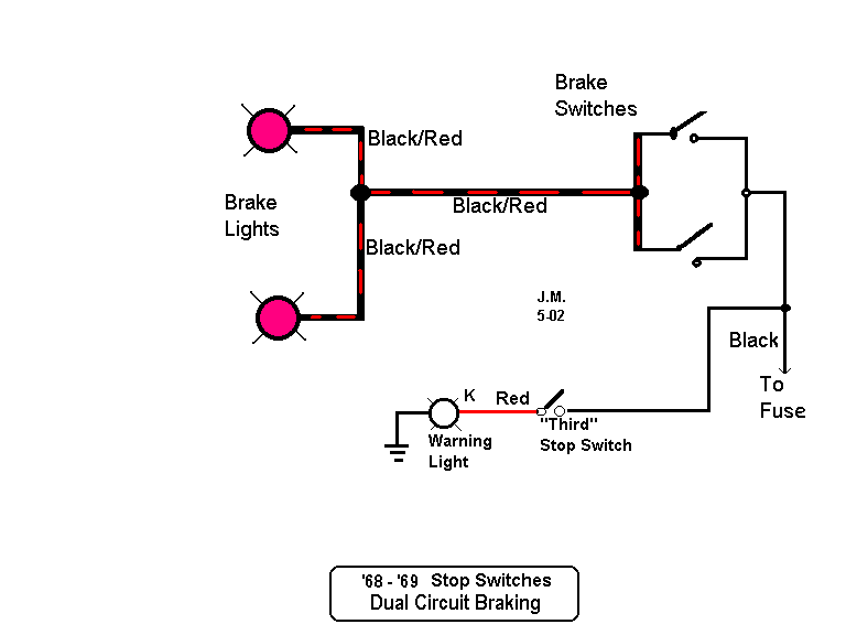
Brake Light Switch Wiring Diagrams are a crucial component of any vehicle’s electrical system. These diagrams provide a visual representation of how the brake light switch is wired, helping mechanics and DIY enthusiasts understand the connections and troubleshoot any issues that may arise.
Why Brake Light Switch Wiring Diagrams are Essential
Understanding Brake Light Switch Wiring Diagrams is essential for several reasons:
- Ensure proper installation of the brake light switch
- Troubleshoot electrical issues related to the brake lights
- Identify faulty connections or components
- Ensure compliance with safety standards
How to Read and Interpret Brake Light Switch Wiring Diagrams
Reading and interpreting Brake Light Switch Wiring Diagrams may seem daunting at first, but with some guidance, it becomes easier:
- Understand the symbols and colors used in the diagram
- Follow the flow of the wiring from the power source to the brake light switch
- Note the connections and components along the circuit
- Refer to the legend for any specific instructions or details
Using Brake Light Switch Wiring Diagrams for Troubleshooting
Brake Light Switch Wiring Diagrams are invaluable tools for troubleshooting electrical problems:
- Identify potential causes of brake light failures
- Locate and test specific wires and connections for continuity
- Pinpoint the source of a short circuit or open circuit
- Verify the functionality of the brake light switch
Importance of Safety
When working with electrical systems and using wiring diagrams, safety should always be a top priority:
- Wear appropriate protective gear, such as gloves and safety glasses
- Disconnect the vehicle’s battery before working on the electrical system
- Avoid working on wet or damp surfaces
- Follow manufacturer’s instructions and safety guidelines
Brake Light Switch Wiring Diagram
Brake Light Switch Circuit Wiring Diagram

Basic Brake Light Switch Wiring Diagram

The Ultimate Guide: E36 Brake Light Switch Wiring Diagram

Brake Light Circuit Diagram

[DIAGRAM] Fj Cruiser For Brake Light Switch Wiring Diagram – MYDIAGRAM
![Brake Light Switch Wiring Diagram [DIAGRAM] Fj Cruiser For Brake Light Switch Wiring Diagram - MYDIAGRAM](http://www.thumpertalk.com/uploads/monthly_09_2014/post-198959-0-87748100-1410466744.jpg)
E36 Brake Light Wiring Diagram
