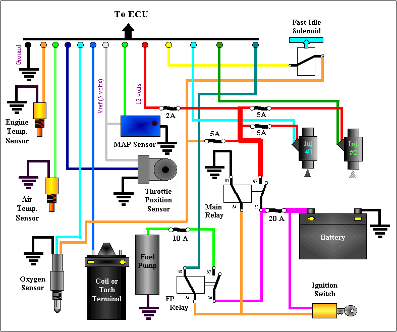
When it comes to diagnosing and fixing electrical issues in a vehicle, having access to an Ecu Wiring Diagram can be incredibly helpful. An Ecu Wiring Diagram is a visual representation of the electrical connections and components within the Engine Control Unit (ECU) system of a vehicle. This diagram shows the wiring layout, color codes, and connections between various sensors, actuators, and other components.
Why Ecu Wiring Diagrams are essential
Understanding Ecu Wiring Diagrams is essential for several reasons:
- Helps in identifying and locating electrical components within the ECU system.
- Aids in diagnosing electrical issues, such as shorts, open circuits, or faulty connections.
- Provides a roadmap for making modifications or upgrades to the electrical system.
How to read and interpret Ecu Wiring Diagrams effectively
Reading and interpreting Ecu Wiring Diagrams can seem daunting at first, but with practice, it becomes easier. Here are some tips:
- Start by familiarizing yourself with the symbols and color codes used in the diagram.
- Identify the power source, ground connections, and signal paths within the diagram.
- Follow the flow of the wiring diagram to understand how different components are connected.
Using Ecu Wiring Diagrams for troubleshooting electrical problems
Ecu Wiring Diagrams are invaluable tools for troubleshooting electrical problems in a vehicle. Here’s how you can use them effectively:
- Trace the wiring connections to identify any loose connections, damaged wires, or faulty components.
- Use a multimeter to test the continuity and voltage at different points in the system.
- Compare the actual wiring with the diagram to spot any discrepancies or errors.
It’s important to note that working with electrical systems can be dangerous if proper precautions are not taken. Here are some safety tips and best practices to keep in mind:
- Always disconnect the battery before working on any electrical components.
- Avoid working on electrical systems in wet or damp conditions.
- Use insulated tools to prevent accidental shorts or shocks.
- If you’re unsure about any aspect of the wiring diagram, seek guidance from a professional mechanic or electrician.
Ecu Wiring Diagram
Ka24e Ecu Wiring Diagram

Ecu Nissan Wiring Diagram Color Codes – Wiring Diagram

Suzuki Jimny Ecu Wiring Diagram
2005 Nissan Maxima Ecm Wiring Diagram – Wiring Diagram and Schematic Role

Complete Guide: 2001 Honda Civic ECU Wiring Diagram for Easy

Engine Ecu Wiring Diagram
