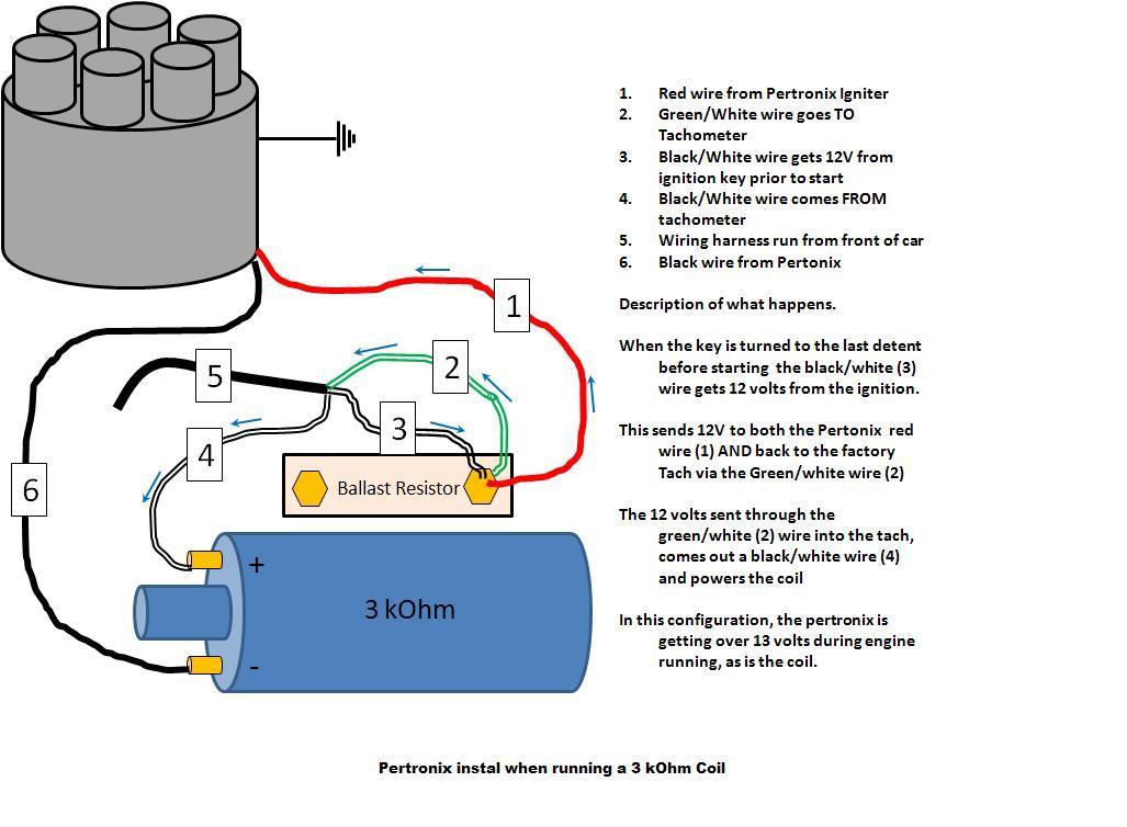
Pertronix Ignition Wiring Diagrams are essential tools for understanding the electrical connections in a Pertronix ignition system. These diagrams provide a visual representation of how the various components of the ignition system are wired together, helping mechanics and enthusiasts troubleshoot issues and make necessary adjustments.
Why Pertronix Ignition Wiring Diagrams are essential
- Helps in understanding the layout of the ignition system
- Aids in diagnosing and fixing electrical problems
- Ensures proper installation of components
- Provides a reference for future maintenance and upgrades
How to read and interpret Pertronix Ignition Wiring Diagrams
When looking at a Pertronix Ignition Wiring Diagram, it’s important to pay attention to the symbols and color codes used to represent different components and connections. Follow the lines and arrows to trace the path of the electrical current and understand how power flows through the system. Refer to the legend or key provided on the diagram to decipher any unfamiliar symbols or abbreviations.
Using Pertronix Ignition Wiring Diagrams for troubleshooting
- Identify potential sources of electrical problems
- Check for loose or damaged connections
- Verify proper grounding and voltage levels
- Compare the actual wiring to the diagram to spot any discrepancies
Importance of safety when working with electrical systems
Working with electrical systems can be dangerous if proper precautions are not taken. Always disconnect the battery before working on any wiring to prevent electrical shock or fire. Use insulated tools and wear protective gear, such as gloves and safety goggles, to minimize the risk of accidents. If you are unsure about any aspect of the wiring diagram or feel uncomfortable handling electrical components, seek help from a professional mechanic.
Pertronix Ignition Wiring Diagram
Pertronix Ignitor Wiring Diagram

PerTronix Electronic Ignition Systems | The Aftermarket's Finest

Pertronix Ignitor Wiring Diagram – Wiring Diagram

Pertronix Wiring Diagram With Factory Tach

Pertronix Ignitor Wiring Diagram – Cadician's Blog

Pertronix Wiring Diagram – Wiring Diagram Pictures
