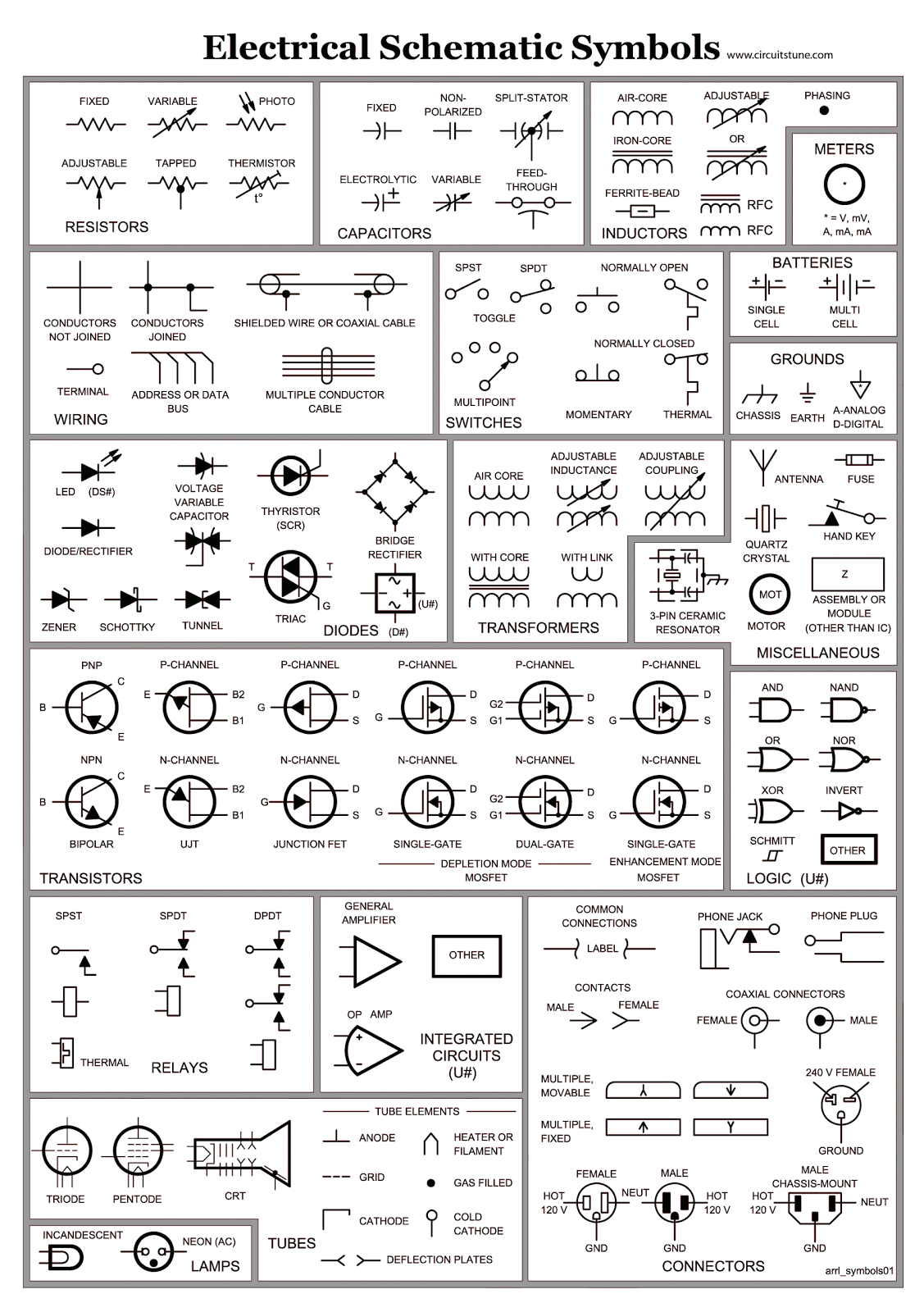
Wiring Schematics Symbols are crucial for understanding electrical diagrams and blueprints in the automotive and electrical engineering industries. These symbols provide a standardized way of representing components and connections in a schematic diagram, making it easier for technicians and engineers to interpret and analyze complex electrical systems.
Importance of Wiring Schematics Symbols
- Ensure consistency and clarity in electrical diagrams
- Facilitate communication between engineers, technicians, and electricians
- Aid in troubleshooting and diagnosing electrical issues
- Help in designing and constructing new electrical systems
Reading and Interpreting Wiring Schematics Symbols
When reading wiring schematics symbols, it is important to familiarize yourself with common symbols used in electrical diagrams. These symbols represent various components such as resistors, capacitors, switches, motors, and connectors. Understanding these symbols will help you decipher the wiring diagram and identify the different components and their connections.
Using Wiring Schematics Symbols for Troubleshooting
Wiring schematics symbols play a vital role in troubleshooting electrical problems. By following the symbols and tracing the electrical connections, technicians can identify faulty components, loose connections, or short circuits. This systematic approach helps in diagnosing and fixing electrical issues efficiently.
Importance of Safety
Working with electrical systems can be dangerous, and it is essential to prioritize safety when using wiring diagrams. Here are some safety tips and best practices to follow:
- Always turn off the power supply before working on any electrical system
- Use appropriate protective gear such as gloves, goggles, and insulated tools
- Avoid working on live circuits or equipment unless necessary
- Double-check the wiring diagram and connections before energizing the system
- Seek assistance from qualified professionals if you are unsure about any electrical work
Wiring Schematics Symbols
Basic Electrical Wiring Diagram Symbols

Electrical Schematic Symbols ~ CircuitsTune

All Electrical Schematic Symbols

The Ultimate Guide to Understanding Wiring Schematic Symbols

Basic Wiring Diagram Symbols
.jpg)
How To Read Electrical Schematic Symbols
